Circuit snippets
Some useful snippets for use in electronics projects.
Attenuverter
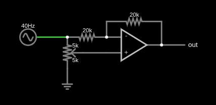
The gain figure is given by $$V_{out}=(2p-1)\cdot V_{in}$$ where $0\leq p\leq 1$ is the proportion of $V_{in}$ fed into the op-amp's noninverting input. Note also that the original schematic called for a 1k resistor between the op-amp's output and the out jack, but I forgot to include it in the figure. Such a resistor is ideal for limiting the output current in case the output is shorted.
Gate-to-trigger converter
The resistor and capacitor form a differentiator with a 390 μs time constant (alternatively, a high-pass filter with $f_{3dB}\approx 408$ Hz). The diode between the comparator's noninverting input and ground provides a path for the negative spike out of the capacitor on the gate's falling edge (see Fig 1.43 in The Art of Electronics, 3ed). The diode on the output prevents the comparator from sinking current once its output is pulled to the negative rail. 1)

