AFT fiber tracer
- status:
- active
- oneline:
- a tool for tracing fiber optic lines
I have on occasion required a tool for identifying fiber optic lines at work. While it isn't often enough to justify the expense of a proper fiber test device, it might be within my capabilities to construct a basic fiber “toner” set.
The project's working title is AFT (Arduino Fiber Tracer or Adequate Fiber Tracer or AFT Fiber Tracer).
Background
Necessity
SFP modules
SFPs (small form-factor pluggable) are compact IR transceivers designed for fiber optic networking. There are two major advantages to using an SFP in this device. First, it puts the tester on equal footing with the devices in the live environment. We don't have to worry about propagation distances; if the SFP-equipped tester can't transmit over the entire fiber run, then neither will a switch be able to. Second, it allows the tester to check the SFP itself using DDM/DOM [1] or I2C [2]. In the future, we may also be able to program the tester to talk to live network devices to help determine where the other end of the cable goes1).
The electrical pinout is shown in Table 1.
| Pin | Name | Function |
|---|---|---|
| 1 | VeeT | Transmitter ground |
| 2 | Tx_Fault | Transmitter fault indication |
| 3 | Tx_Disable | Optical output disabled when high |
| 4 | SDA | 2-wire serial interface data line (using the CMOS EEPROM protocol defined for the ATMEL AT24C01A/02/04 family [3]) |
| 5 | SCL | 2-wire serial interface clock |
| 6 | Mod_ABS | Module absent, connection to VeeT or VeeR in the module indicates module presence to host 2) |
| 7 | RS0 | Rate select 0 |
| 8 | Rx_LOS | Receiver loss of signal indication |
| 9 | RS1 | Rate select 1 |
| 10 | VeeR | Receiver ground |
| 11 | VeeR | Receiver ground |
| 12 | RD- | Inverted received data |
| 13 | RD+ | Received data |
| 14 | VeeR | Receiver ground |
| 15 | VccR | Receiver power (3.3 V, max. 300 mA) |
| 16 | VccT | Transmitter power (3.3 V, max. 300 mA) |
| 17 | VeeT | Transmitter ground |
| 18 | TD+ | Transmit data |
| 19 | TD- | Inverted transmit data |
| 20 | VeeT | Transmitter ground |
The Tx_disable pin is connected to an internal pull-up resistor inside the module. This pin must be pulled low to enable the transmit laser.
Osmocom SPF experimenter
For the prototypes, we will be using the Osmocom SFP Experimenter board. This breakout contains all support circuitry required to send single-ended signals through an SFP. No restriction is made on the input data, so we need not send valid Ethernet frames. That opens up the question of how we are to encode the data for transmission [4]. Of course, instead of sending arbitrary bits, we could instead transmit a clock. There's no need to encode the data ourselves—just use hardware UART pins.
For whatever reason, the SFP Experimenter board is designed to accept I/O connections through SMA connectors (one per stream). The units ship without the connectors soldered to the board, so we can add whatever kind of interface we want—simple wires will do.
The I2C bus on the board already includes pull-up resistors, so no external pull-ups are required.
SFP data registers
SFP modules expose a great deal of data detailing their internal status, all accessible through I2C at one of two addresses (0xA0, 0xA2). Before data can be read, the EEPROM address must be loaded in by performing a dummy write containing the 8-bit EEPROM address to retrieve. For example, the device vendor name is stored in 16 bytes at I2C address 0xA0, EEPROM address 20. The following snippet demonstrates this procedure.
// load in the EEPROM address
Wire.beginTransmission(0x50);
Wire.write(20);
Wire.endTransmission();

// request the data
Wire.requestFrom(0x50, 16);
// data is now ready for read(), see docs
After each read, the internal address register is incremented so it points to the next byte. Given the way we're most likely to access this table, this fact is of relatively little use to us.
| Value | Address (dec) | Data length |
|---|---|---|
| Manufacturer name (ASCII) | 20 | 16 |
| Compliance code | 3 | 8 |
| Nominal signalling rate (100s Mbd) | 12 | 1 |
| Supported optional DDM features | 93 | 1 |
| Value | Address (dec) | Data length |
|---|
Serial data transmission
Design
The idea is to have a pair of Arduino-based devices. For a given test session, one (designated the toner) is connected the the line under test and begins transmitting a particular signal. The other (designated the probe) watches for this signal. Once it finds the signal, it can send a reply back to confirm that the toner is indeed on the other end. Each device should be equipped with a display and some kind of controls for communicating with the user.
User interface
User I/O can be provided over I2C with an Adafruit RGB LCD shield. The LCD color can be used to indicate status (e.g., red = no SFP, green = paired, yellow = sending) to free up screen space. The shield also includes a four-way directional keypad and select button3).
Operation is split into two primary modes: SFP diagnostic and tone. SFP diagnostic mode gets a subset of device parameters from the SFP over I2C [5] and displays it on the screen. Each page indicates the parameter name on the top row and the value (with units) on the bottom row. Tone mode transmits a signal through the SFP and watches for a return signal. If the partner device is detected, the screen lights green and a success message appears. The SELECT button cycles through modes.
If space permits, a serial debug mode would be handy. This mode would accept commands (possibly binary data for efficiency) over USB and offer direct read/write access to the hardware. It should probably be accessible only through a key combination.
Firmware
On startup, the tester initializes I/O devices, prints a splash screen, and drops into SFP diagnostic mode.
At the beginning of the main loop, the tester verifies that an SFP is present. If not, we call a function to display a warning message, turn the screen red, and busy wait. Once an SFP is inserted, the tester gets button status, setting the appropriate action flags (on arrow buttons) or updating the mode byte (on SELECT button). That mode byte then determines what happens for the rest of the loop.
| Value | Mode |
|---|---|
0x00 | SFP diagnostic |
0x01 | Tone |
0x02 | Probe |
0xFF | USB debug |
SFP diagnostic mode uses an offset into a table to determine which parameter to load from the SFP. If the user pressed UP or DOWN, then that offset is adjusted accordingly before the read. Once read, the parameter name is printed to the top row, and the parameter value is scaled as necessary and written to the bottom row (with units if applicable).
The tone functionality is bisected into two modes. We call these “tone” and “probe” by analogy to a copper tone and probe set. The unit in tone mode continuously transmits a signal4) on the wire and awaits a return. The unit in probe mode watches for the toner's signal and transmits its own in return. Once a tester is both transmitting and receiving, the LCD lights green and indicates a connection.
In USB debug mode, the user can send commands to the tester and inspect its internal state. This mode should only be accessible by holding the mode select button to prevent accidental activation.
Prototyping
-
2x
Arduino Uno Rev3 (\$28)Arduino Leonardo
We don't want to rely on the Osmocom SFP Experimenter board for the final product, but it has the major advantage of a built-in differential transmitter and receiver5).
Table 4 indicates proposed pin connections. Underlined items are ideally suited for interrupts6).
| Device pin | Arduino pin | ||
|---|---|---|---|
| LCD | |||
| RX | ← | D8 (SoftwareSerial) |
|
| +5V | ← | +5V | |
| GND | ← | GND | |
| SFP Experimenter | |||
| +3.3V | ← | +3.3V | |
| GND | ← | GND | |
| RX | → | D0 (Serial1) |
|
| TX | ← | D1 (Serial1) |
|
| SDA | ↔ | SDA/D2 | |
| SCL | ↔ | SCL/D3 | |
| TX_FAULT | → | D5 | |
| MOD_ABS | → | D4 | |
| Rotary encoder | |||
| Enc A | → | D18 | |
| Enc B | → | D19 | |
| GND | ← | GND | |
| Sw A | → | D17 (INPUT_PULLUP) |
|
| Sw B | GND | ||
Communication
UART transmission is not looking terribly promising at this time.
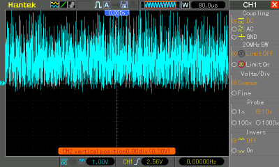
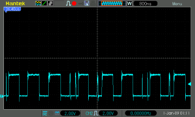
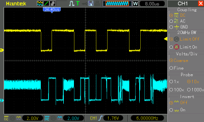
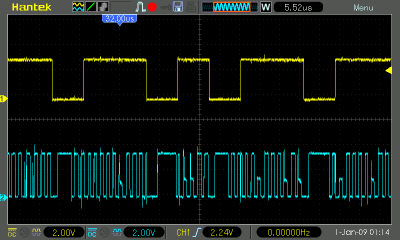
Different SFP models appear to produce different signals when the output is open. The SMF unit (unknown vendor) outputs nothing, while the Veloso units send (noisy) pulse trains (see Figure 1). They also respond differently to inputs, with the former producing an inverted replica of the input and the latter outputting what might be PWM (Figure 2).


k at 115200 baud, 8N1
Power considerations
Portable operation is a must for this tester.
Relevant links
-
I2C LCD shield kit with keypad (LCD not included)
-
a card edge connector that might actually work; the EDAC 395 series (specifically 395-020-558-xxx models or 395-020-520-201) are also promising
-
the Feather platform might also be a viable brain for this project; the 32u4 model is software/pin compatible with Arduino and features built-in battery connections and monitoring
-
the Teensy 4.1 may also be a good production brain; it's also compatible with Arduino, has many more interrupt pins; if we use the model with Ethernet header and connect a matching jack, we might be able to use it to tone out copper lines as well (as long as they're not energized)
References
tone()/pulseIn() for this signal. The probe calculates the parameters and generates its own signal, and the toner measures the incoming signal to see if it matches the outgoing. We could cycle through parameter values using the arrow keys, in theory allowing us to use multiple toners and have the probe tell us which it's connected to.